Planning Space for Pipe Organs
Introduction
This booklet is intended to aid in planning for the installation of a pipe organ. It answers questions often asked regarding basic components, placement of the organ, and technical requirements. We encourage establishing a dialogue between architect and organ builder. This communication from the earliest stages is vital to the success of the project. Any high quality organ builder will be glad to assist in the design phases.
Variety in Pipe Organs
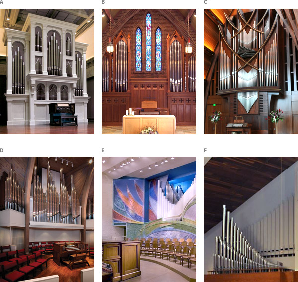
The pipe organ can be designed and installed in a variety of ways depending on the style of the room and the musical needs of the organ purchaser. The following page illustrates a number of different possibilities of organ installations. Organ components can be housed in a case with compartments in which display pipes are mounted (see photos A, B, and C). Or they can be arranged to create an open design (see photos D, E, and F).
The components of the modem pipe organ can be divided into three main categories:
- pipes/windchests
- console
- blower
The pipes are placed on windchests which operate them. The pipes and windchests; must be located together. The console (keyboards and stop controls) operates the windchests. It may be attached to the pipes/windchests (in which situation it is often called a keydesk) or it may be in its own case a short distance away. Likewise, the blower may be housed with the pipes/windchests, but is often preferred to be in a remote location. While there are many other secondary components to the pipe organ, these three items are common to all instruments and are the most important to consider in planning space. Questions regarding specifics of the components are best left for discussion with specific builders, but some helpful information is presented later on.
The heart of every pipe organ is of course the wind-blown pipes which are arranged in an instrument by ranks. A rank is a set of pipes of the same tone (e.g. a rank of oboes, or a rank of flutes). Each pipe in the rank corresponds to a key on the keyboard. A rank may contain 32 pipes for pedal ranks or 61 pipes for manual ranks. The ranks of pipes stand on windchests, which are wooden boxes containing wind (air under pressure). When valves in the windchests are activated by the organist at the console, the wind enters the pipes causing them to speak.
A rank of pipes is only capable of producing one type of sound at one volume. Therefore to provide a variety of sounds and volume levels, pipe organs consist of different ranks of pipes that can be played either alone or in combination with other ranks to create varying possibilities of sound.
The size of a pipe organ is stated in the number of ranks. The term stop (or voice or register) is often synonymous with rank, but sometimes a stop will comprise several ranks. Stop also refers to the controls on the console which turn on the ranks, hence "pulling out all the stops." The number of keyboards, called manuals, is also used to indicate the size of a pipe organ. Size varies significantly from one organ to the next and is generally governed by the size of the room. The chart "General Guidelines for Pipe Organ Size", found in Chapter 7, lists information concerning approximate recommended sizes, and is only to be used as a general guide.
Acoustics
Planning a room with good acoustical properties is important, not only for the pipe organ but for all music (instrumental or choral) and the spoken word. To insure the desired results, it is often wise to retain the services of an acoustical engineer. Look for one who understands the requirements of successful musical acoustics as well as clear speech intelligibility. Seek out one who has demonstrated that understanding in church buildings you can visit.
It is important to plan for a room that has pleasant, responsive, resonant acoustical properties. An even reverberation time of 2 - 3 seconds with the building half occupied is a practical goal. While it is possible to build a successful instrument in conditions less favorable than this, it is not the most desirable situation. One general rule to achieve this is to allow a minimum of 250 cubic feet of volume for every person. A room should be equally responsive in all frequency ranges.
The acoustic response of the room is determined initially not only by its cubic volume, but also by its shape and its materials. A rectangular plan with high flat ceiling is best. Sidewalls which are too low not only reduce cubic volume but force undesirably low positioning of the organ pipes.
Hard reflective surfaces (floor, walls, and ceiling) will promote better sound reflection. Choose all finish material carefully. Sound absorbing material (pew cushions, carpet, etc.) should be avoided. Floor surfaces of hardwood, concrete, tile or marble are most desirable. Walls of stone or smooth brick are ideal. Generally, the more solid the material, the better the results. Ceilings should also be hard surfaced. Porous materials should be avoided. If such material is desirable for visual reasons, it should be sealed with a polyurethane sealer. It is especially important to provide rigid materials near the choir and organ areas. This will contribute greatly to the total effect of the room. Sound diffusion, the desirable, even distribution of sound throughout a room, is in part created by architectural details such as pilasters, beams, moldings and reveals. Irregular wall and ceiling surfaces also promote sound diffusion and should be incorporated into the design of a room if possible.
Remember the following points in planning a good room: Plan for responsive acoustics with a natural reverberation. Surfaces (floor, walls, ceiling) should be constructed of solid, hard, acoustically reflective materials with sound diffusing elements. Avoid sound absorbing materials. Minimum cubic volume = 250 cu. ft. per person.
Location of the Pipe Organ
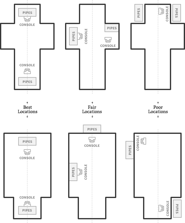
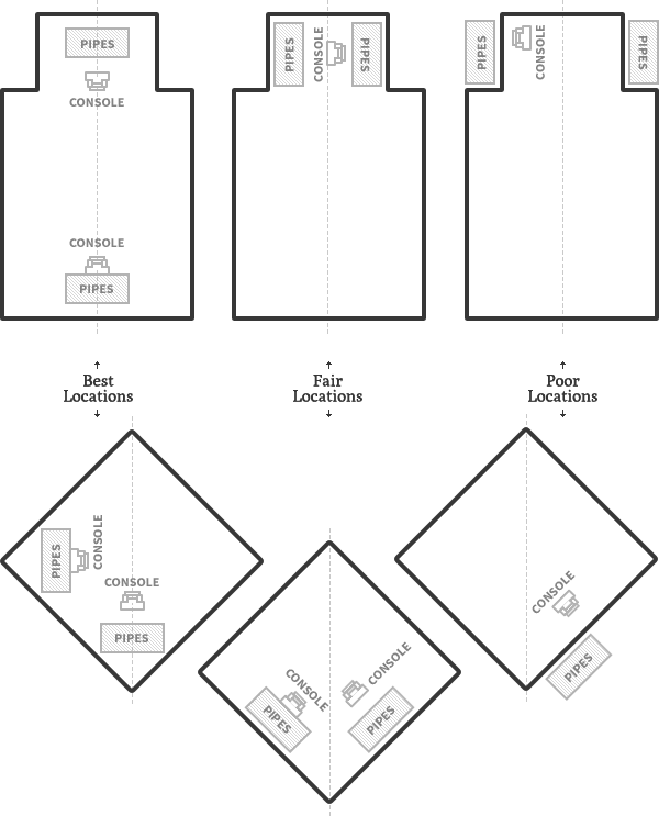
The pipe organ is a wind-blown instrument. To allow the instrument to fill the room naturally with a musical tone, pipes/windchests should be located prominently without obstacles to sound distribution. The location on the central axis of the room is ideal. The farther away from the central axis and the more barriers to egress of sound, the less desirable the location.
The function of the instrument is important in deciding where it should be located. If the organ will be used to accompany choral singing, the pipes, and choir should be located as close together as possible. The location of the console should ensure good sight lines between the organist and the choir, chancel, and altar.
If the instrument is in a concert hall, the organ should be placed to provide good sight lines between the conductor, the organist and the instrumentalists.
Remember the following:
- Locate the pipes as intimately as possible on the central axis of the room.
- Maintain good sight lines for the organist at the console.
- Locate the choir and pipes/windchests in the same area of the room.
- The pipes/windchests should be located above and behind the choir or orchestra members.
The following are typical examples of organ locations:
purchasing_guide_organ_placements
Image 1. Sitting Organs in Typical Buildings
planning_space_organ_placements_2
Image 2. Sitting Organs in Typical Buildings Continued
Components of the Pipe Organ
Details of pipe organ construction are best learned from a pipe organ builder; however, the following general information is offered as a primer.
The three basic elements of a pipe organ were mentioned on page 2 and are covered in more detail below. Another important element is the method of connection between console and pipes/windchests. This is called the action. The type of action employed determines to a great extent the layout of the organ components. There are two types of action in general use today.
Action
Mechanical Action
Mechanical action organs, or tracker organs as they are commonly called, are usually built within a wooden cabinet called an organ case which is located within the room. Tracker organs have many direct mechanical connections between the console and the pipes/windchests. The console is usually built into the lower front of the organ case and is called the keydesk.
Mechanical action organs sometimes employ a separate or detached console. When this configuration is used, the mechanical connections between the console and the organ case are installed in a chase which is on or built into the floor. A chase size of 16" high by 60" wide is adequate for most installations. The organ builder will provide more specific requirements.
Electric Action
Electric action organs are built either within an organ case or located within organ chambers or other space provided within the room. The action between the keyboards and the windchests is electrical, operating on 10 to 3 0 volts direct current. Therefore a detached console is often used. The linkage between the console and the pipes is a flexible electrical cable, so the console can be placed in the most convenient location to suit the needs of the church. However, care should be taken to avoid excessive distance. The console may also be mounted on a movable platform, or casters.
The Pipes/Windchests
You can see the arrangement of pipes/windchests in a mechanical action organ and an electric action organ in the "Cross Section of an Encased Organ" diagrams in Chapter 5. The configuration and arrangement may vary from builder to builder but the space necessary for the instrument is somewhat universal.
The space required for a mechanical action organ is defined by the size of the case. The weight is borne on the footprint area of the case and floor loads can vary from 50 lbs/sq.ft. to as much as 1,000 lbs/sq.ft. for a large instrument with a small footprint.
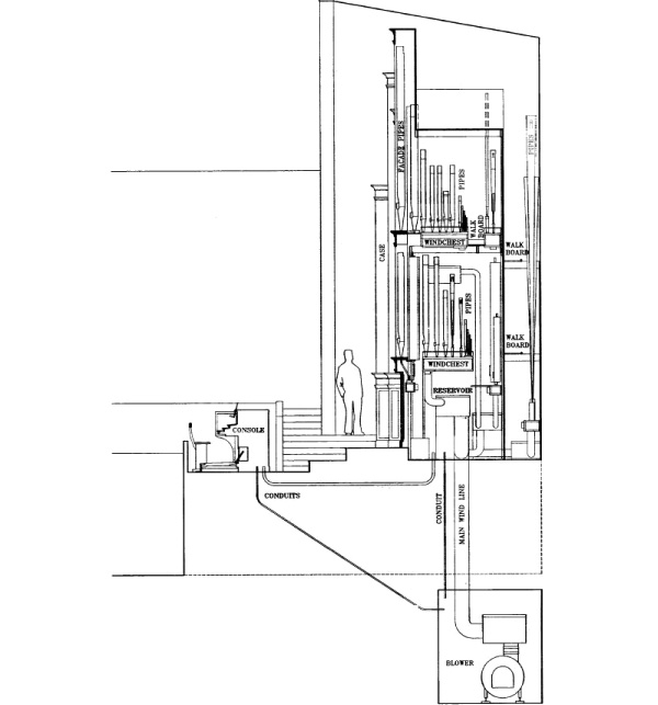
planning_space_cross_section_electric
Cross Section of an Encased Organ (Electric Action)

planning_space_cross_section_electric
Cross Section of an Encased Organ (Mechanical Action)
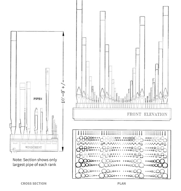
planning_space_10_rank_windchest
A Ten Rank Electric Action Windchest
The windchests are the largest and heaviest component to be considered in the layout of an electric action organ. They are approximately 8' to 10' in length and vary in width depending on the number of ranks. The floor in the area where these parts are located should be capable of supporting 450 to 500 lbs per rank. This generally means floor loads of 50 to 100 lbs/sq.ft. However, weight can be concentrated or distributed and can affect the support needed. The organ builder should be consulted for specific information.
It is important to consider that access to these components is required for regular tuning and service. The chart "Average Console Size and Weights" below gives some handy references to size and weight of pipes/windchests.
The Console
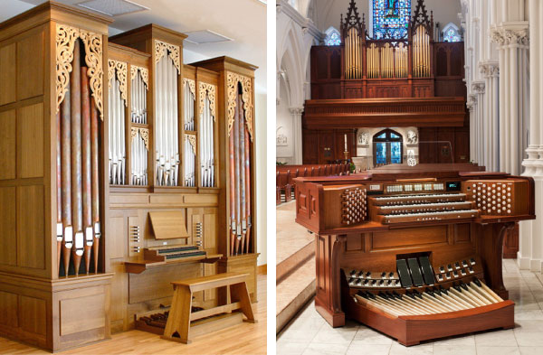
planning_space_consoles
Left: Attached console (often called keydesk) Right: Detached Console
Average Console Size and Weights:
| MANUALS | Width | Depth | Height | Weight |
|---|---|---|---|---|
| 2 (small) | 5' | 5' | 3'9" | 500 lbs |
| 2 (large) | 6' | 5' | 4'2" | 700 lbs |
| 3 | 6'7" | 5'6" | 4'4" (or more) | 1000 lbs |
| 4 | 6'10" | 6' | 4'8" (or more) | 1300 lbs |
What portion of the selling price is represented by the actual cost of labor and materials used to produce the product? In other words, what is the organ's real substance?
Pipe organ builders are just that ‐ builders, not marketers. The bulk of the price you pay is for high quality materials and expert workmanship. There is very little margin for profit, sales commissions, advertising, fancy brochures, and the like. Electronic organ companies must pay to maintain marketing departments, sales forces, retail store operations, and national advertising. All this must be deducted from the price of the instrument to find its value. Electronic organs are priced exactly like other household appliances, allowing for huge profit margins. You simply get more for your money with a pipe organ.
The Blower
All pipe organs must have a system to deliver wind (pressurized air) to the windchests. The air is pressurized by a motor-driven centrifugal blower. It is ideally located in an acoustically isolated area in order to prevent mechanical noise from being transmitted into the room where the organ is to be heard. The air should be filtered and drawn from the room where the pipes/windchests are located. A wind trunk or wind line must be supplied from the blower to the organ and this is normally the responsibility of the purchaser.
The wind lines required range from 6" to 15" in diameter with 8" to 12" being typical. It is essential that all seams in the wind lines be air-tight and should be formed with lapping in the same direction as the wind's travel. Taped joints are not sufficient. Whatever their material, wind lines should be capped at both ends during the building construction process to keep the lines free from dust and debris. Lines running through unheated/uncooled space should be insulated. Lines should be terminated 6" to 12" inside the blower room and the organ area. Wind lines may be either 24 gauge galvanized or PVC pipe if local building codes permit.
Electrical Requirements
Pipe organ systems which require electricity are the blower, work lights, console lights, work outlets, and action current rectifier. Since these components and current ratings vary significantly from instrument to instrument, specific electrical questions must be directed to the organ builder. Blower motors range from 1/4 to 10 horsepower depending upon the size of the instrument.
Preliminary planning for electrical service should take the following into consideration:
1. Blower(s)
- One dedicated circuit per blower; normally 110v. for small organs, 220v. for medium to large instruments.
2, Three phase power preferred for blowers over 1 h.p.
- Light Fixtures: (at pipes/windchests)
One or two dedicated circuits.
3. Duplex Receptacles: (at pipes/windchests)
- One or two dedicated circuits (may share a circuit with #2 above in small instruments.)
4. Light Fixtures: (at console)
- One dedicated circuit.
5. Rectifier: (usually located with main blower)
- One to four dedicated circuits required. Some mechanical action organs do not require a rectifier.
6. Rectifier: (at console)
- One or two dedicated circuits. Some organs do not require a console rectifier.
The rectifier runs on A.C. current and provides the 10-30v. D.C. current to operate internal components of the console and windchests. The organ builder will normally provide any necessary rectifiers and all D.C. wiring in the organ. The purchaser is responsible for the hookup of all A.C. wiring during the organ installation.
Most electric action organ builders require that the purchaser install conduits between the major components of the organ (console, pipes/windchests and blower) in which A.C. and D.C. wiring can be run. Here are some general guidelines, although requirements vary significantly:
- Provide a 3" empty conduit from the console to each area where pipes/windchests are located (including remote locations such as antiphonal or echo divisions). These will be used for the organ's D.C. wiring
- Provide a 3/4" conduit (with wires) from the console to each blower location (including any remote locations). These will be used for switching the blower(s) and rectifier(s) on and off from the console.
- Provide one or more 3/4" conduits from an A.C. source (panel board) to the console for lights and/or rectifier.
- Provide a 1" empty conduit from the main blower to the main area of pipes/windchests. This will be used to bring D.C. power from the rectifier to the organ's internal components.
General Guidelines for Pipe Organ Size
(for preliminary planning purposes only)
| Seating Capacity | Total Ranks | # of Manuals | Space Requirements1 | |||
|---|---|---|---|---|---|---|
| Vertical Layout | Horizontal Layout | |||||
| Floor Area2 | Height3 | Floor Area | Height3 | |||
| 100 | 3-10 | 1-2 | 8-10 sq ft per rank | 10'-13' | 8-10 sq ft per rank | 10'-13' |
| 150 | 5-13 | 1-2 | 8-10 sq ft per rank | 13'-17' | 8-10 sq ft per rank | 10'-13' |
| 200 | 11-16 | 2 | 6-8 sq ft per rank | 17'-21' | 5-8 sq ft per rank | 13'-17' |
| 250 | 14-20 | 2 | 6-8 sq ft per rank | 17'-21' | 5-8 sq ft per rank | 13'-17' |
| 300 | 18-24 | 2 | 6-8 sq ft per rank | 17'-21' | 5-8 sq ft per rank | 13'-17' |
| 350 | 22-29 | 2 | 6-8 sq ft per rank | 17'-21' | 5-8 sq ft per rank | 13'-17' |
| 400 | 26-35 | 2-3 | 3-6 sq ft per rank | 21'-25' | 5-8 sq ft per rank | 17'-25' |
| 450 | 30-42 | 3 | 3-6 sq ft per rank | 21'-25' | 5-8 sq ft per rank | 17'-25' |
| 500 | 34-50 | 3 | 3-6 sq ft per rank | 21'-25' | 5-8 sq ft per rank | 17'-25' |
| 600 | 39-57 | 3-4 | 3-6 sq ft per rank | 21'-25' | 5-8 sq ft per rank | 17'-25' |
| 700 | 46-64 | 3-4 | 3-6 sq ft per rank | 21'-25' | 5-8 sq ft per rank | 17'-25' |
| 800 | 50-71 | 3-4 | 3-6 sq ft per rank | 25'-35' | 5-8 sq ft per rank | 17'-25' |
| 900 | 57-78 | 3-4 | 3-6 sq ft per rank | 25'-35' | 5-8 sq ft per rank | 17'-25' |
| 1000 | 65-86 | 4 | 3-6 sq ft per rank | 25'-35' | 5-8 sq ft per rank | 17'-25' |
1Pipes/windchests only; console and blower not included. Includes access areas such as walkboards, and tuning aisle behind encased organs. 2Depth of footprint for pipes/windchests should be between 1/4 and 1/2 of the width for good tonal egress. 3Assumes lowest windchest is 6'0" above floor.
Note: Actual space requirements depend on many things including: type of action, scales (diameters) of pipes, shape of space available, etc.
Bibliography
Anderson, Poul-Gerhard. Organ Building and Design. New York: Oxford University Press 1969.
Audsley, George Ashdown. The Art of Organ Building. New York: Dover Publications, Inc., 1965.
Barnes, William H. The Contemporay American Organ: Its Evolution, Design and Construction. New Jersey: J. Fischer and Brothers, 1964.
Beranek, Leo. Music, Acoustics. and Architecture. New York: John Wiley & Sons, Inc., 1962.
Blanton, Joseph E. The Organ in Church Design. Albany, Texas: Venture Press, 1957.
Blanton, Joseph E. The Revival of the Organ Case. Albany, Texas: Venture Press, 1965.
Hurford, Peter. Making Music on the Organ, Chapter 2. London: Oxford University Press, 1990.
Klais, Hans-Gerd & Philipp. The Siting & Planning of Organs: Guidelines for Architects. Bonn, Germany: Johannes Klais, Orgelbau, 1990.
Norman, Herbert & H. John. The Organ Today. London: Barrie and Rockliff, 1966.
Riedel, Scott. Acoustics in the Worship Space. St. Louis: Concordia Publishing House, 1986.
Williams, Peter and Owen, Barbara. The Organ. New York: W. W. Norton & Company, 1988.
